The OpenGL menu
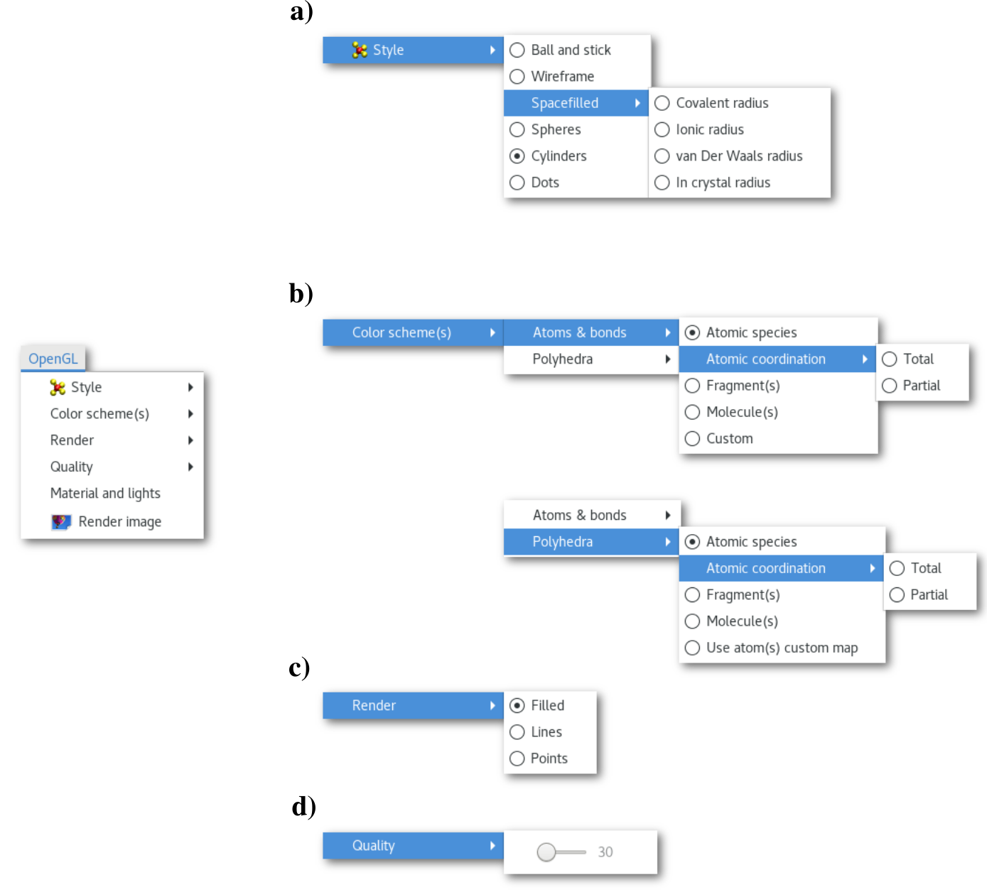
The "OpenGL" menu is detailed in figure 5.2. The behavior of the "Render" menu [Fig. 5.2-c], and the "Quality" menu [Fig. 5.2-d], as well as of the "Render image" button being pretty intuitive the following only detail the behavior of the "Style menu", the "Color scheme(s)" menu [Fig. 5.2-b], and the "Material and lights" button.
The "Style" menu
Using the "Style" menu it is possible to define to default style of the model representation, the options are among the most commonly used in chemistry. Changing the default style from this menu will update several parts of the OpenGL window and associated menus. For instance selecting the "Ball and stick" option will update the first tab of "Atom(s) configuration" dialog [Fig. 5.6] to display atomic radius and the "Bond(s)" menu [Fig. 5.5] to present the "Radius(ii)" and offer a shortcut to modify their values.
It is possible to define local style(s) to improve the visual representation, however this is only possible using the mouse, see section 5.2.2.1, and changing the default style of the model using the "Style" menu will reset/erase any local style(s) value(s) to the default.
The "Color scheme(s)" menu
In the Atomes program when the file is opened most of the bonding properties are calculated "on-the-fly", allowing to gain insights on the atomic coordinations, as well as the number of fragments and the different molecules in the model.
Therefore before using the "Color scheme(s)" menu it is important to be familiar with the following definitions:
Total coordination = total number of first neighbor atoms around the atom.
Partial coordination = number of atoms of each chemical species around the atom.
Fragments = isolated molecular objects in the model.
Molecules = the different topological objects in the model.
Coordination polyhedra = structure drawn by linking the atoms of the first coordination sphere for a particular atom. Requires the considered atom to have 3 neighbors, then the atom it-self is used as a point to build the polyhedra, or more.
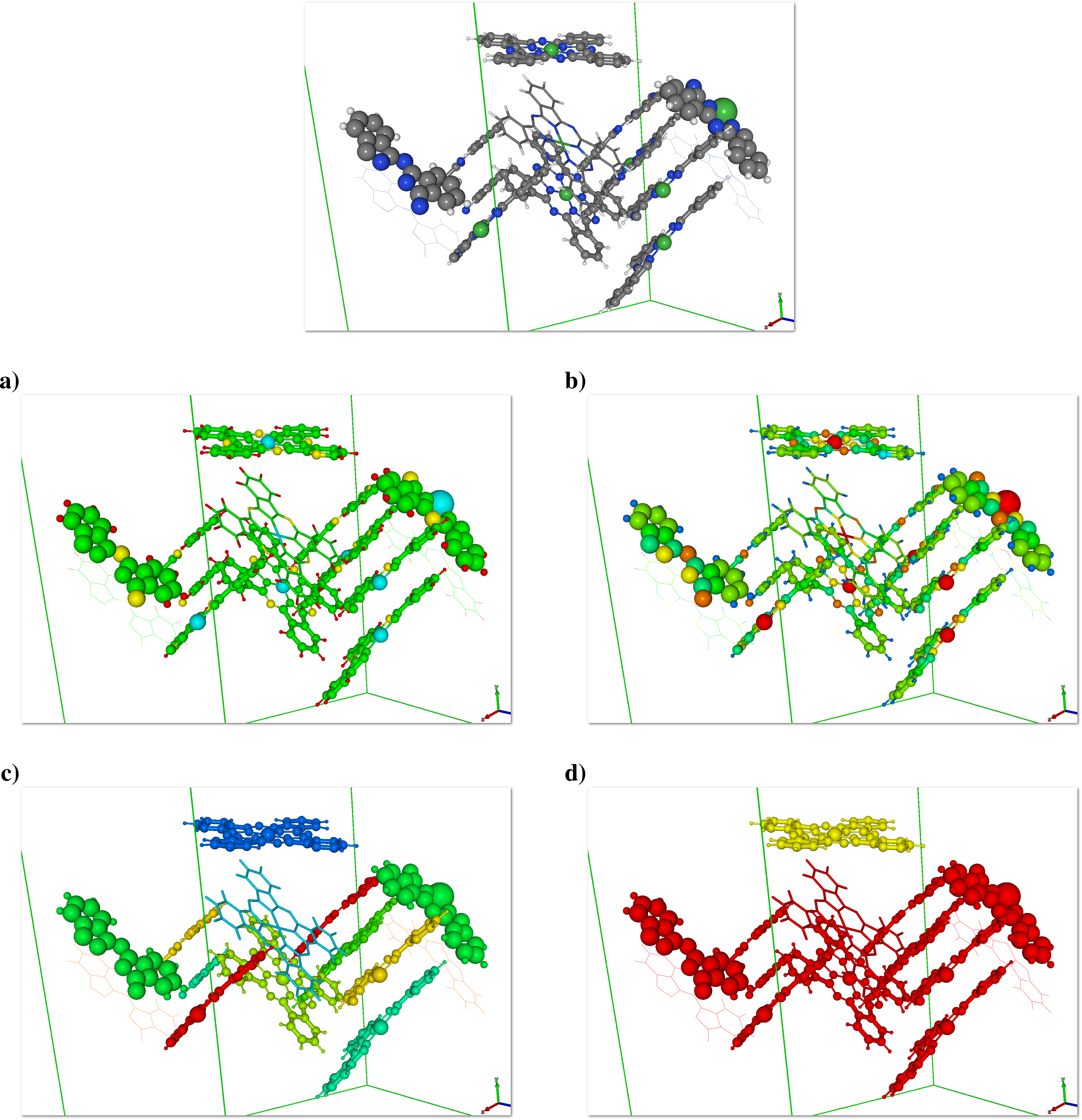
The "Color scheme(s)" menu allows to change the Color Map (CM) for both atoms and coordination polyhedra, based on the bonding analysis performed using the bond cutoff(s) specified by the user. An illustration is provided in figure 5.3 for the "Ni-Phth" project of the example workspace, note that is this model the molecule on the top is missing a hydrogen atom compared to the one that composed the surface.
The colors of each objects can be modified/adapted via the appropriate menus/dialogs (see sections 5.1.2 and 5.1.3).
Using a custom color map
Alternatively to the CMs proposed by the Atomes program it is possible to apply a user defined CM to the OpenGL model, this option is accessible via the "Custom" button of the "Atoms & bonds" menu [Fig. 5.2-b]. In that case it is required to read a file (having the extension "*.dat") that contains the numerical data to be used as color scale. This file must be a simple (Unix like) text file with as many lines as:
Total number of MD steps
Indeed the new colors can be applied to the entire MD trajectory.
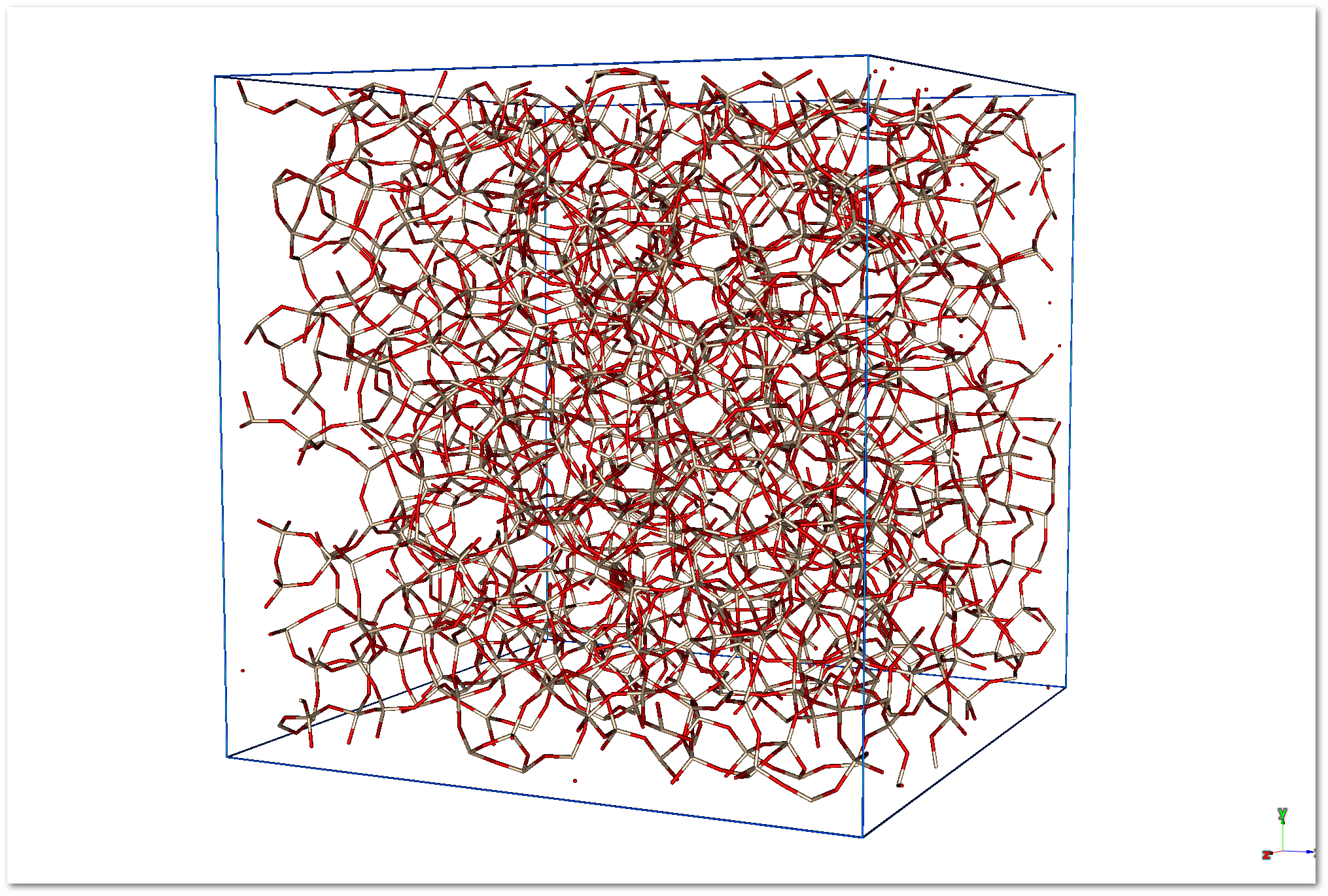
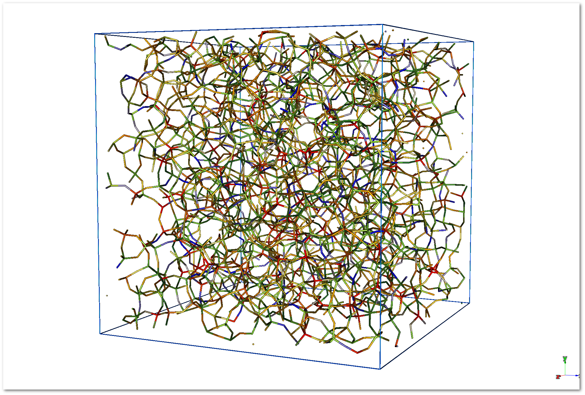
An example is provided hereafter for the silica glass model:
In the initial setup the chemical species are used as color map:
When the "
Custom" button is pressed for the atoms CMs, the "Custom color map setup" dialog appears: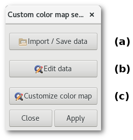
(a) The "
Import / Save data" button allows to import your data file to create the color map. If the data file is processed successfully then Atomes will propose to use it and a confirmation dialog will pop-up: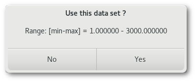
For this example the data points are simply the atom indices from 1 to 3000.
(b) Afterwards using the "
Edit data" button it becomes possible to edit the data in a basic spreadsheet like mode, so that values for a particular atom can be checked and/or modify if needed: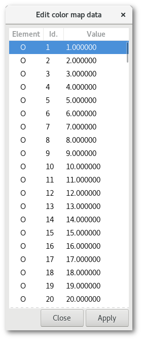
(c) And using the "
Customize color map" button is possible to customize the color map, initially a gradient of red an blue between the maxima and the minima of the values in the data set is used, but you can easily add or remove point(s), and adjust the corresponding color to enhance the visual representation of your model: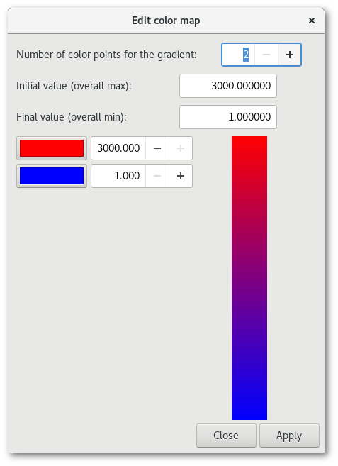
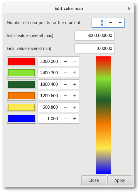
Finally simply apply the changes to use the new colors:
The "
Custom" data and the corresponding color map are saved within the Atomes project and workspace files (see section 3.3.2 and 3.3.3), so that it will not be require to load a prepare the color map between work sessions.
Material and lights
The "Material and lights" button of the "OpenGL" menu opens the "OpenGL material aspect and light settings" dialog [Fig. 5.4]:
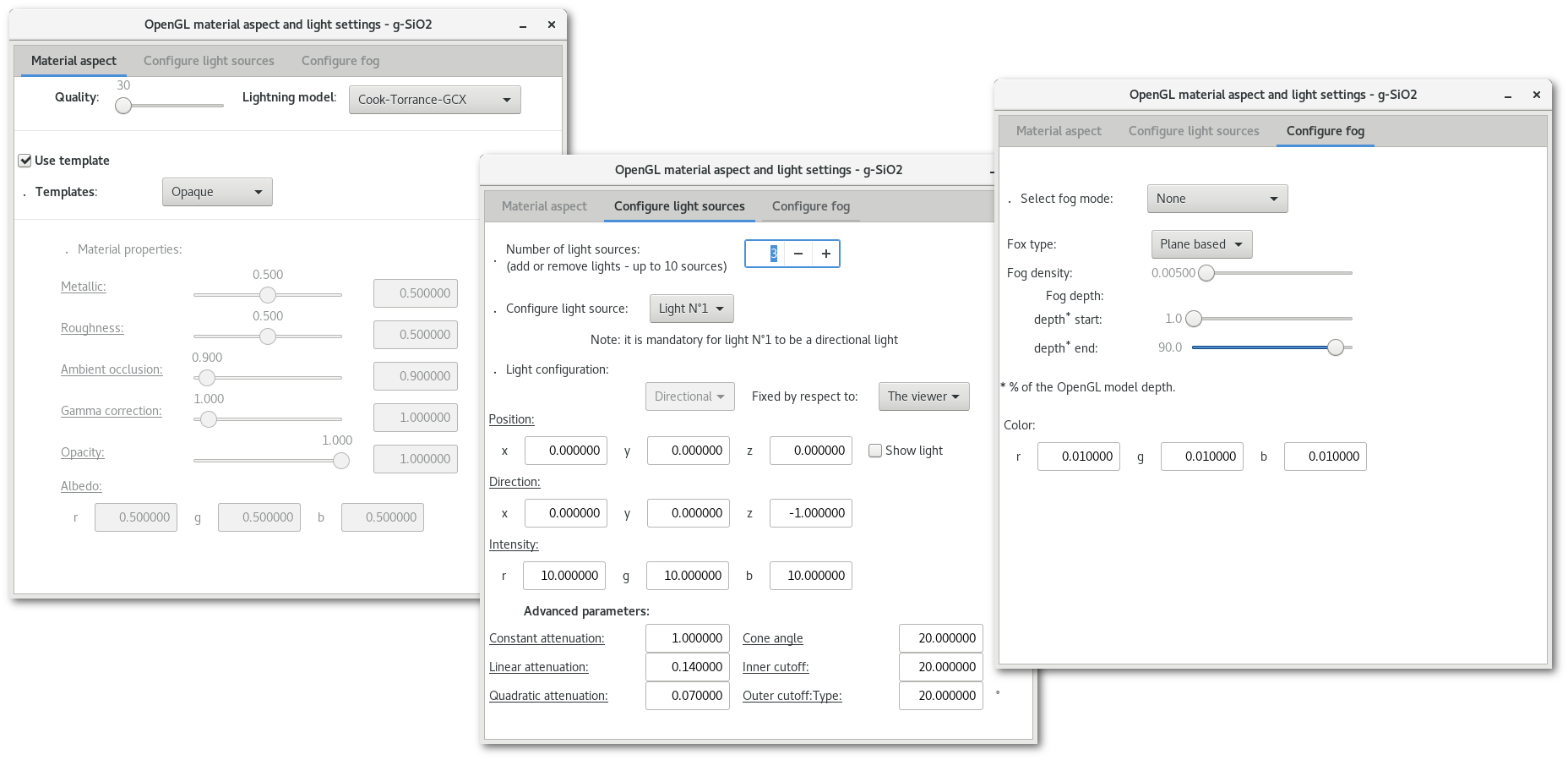
The window contains a notebook with 3 tabs:
The first tab allows to configure/adjust:
The quality of the rendering, ie. the number of polygons to render a volume.
The lightning model, from the lowest quality (fastest to render, "
None") to the highest quality (longer to render, "Cook-Torrance-GCX").The material aspect, few templates being available, but all characteristics required to describe the material aspect for the light mode being available.
The second tab allows to configure the lights sources of the model:
3 type of light source being available: directional, point and spot lights.
With the possibility to add up to 10 light sources.
Finally the third tab is used to adjust the fog effects
For information on OpenGL lightning models, material effects, lights, and more see: